Author: Prof. Roger West, School of Engineering, Trinity College. September, 2022
Novel, low carbon precast sandwich panels for retrofitting, or re-cladding building facades were investigated by a consortium of European partners including UCD, TCD and industrial partners, Techrete. This blog, the second of two will deal with the composite structural action of such panels, whether load-bearing thick panels (such as in figure A below, with a thick inner wythe connected by shear collectors, shown in blue), or thin self-supporting panels (with two thin wythes), which only have to withstand lateral loads, particularly wind loads.
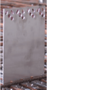
The panels, which could be up to 4m in length, are expected to have flexural resistance by developing composite action between the inner and outer wythes, separated by a thick layer of rigid insulation (shown in yellow in figure A), strengthened by a small number of shear connectors suitably embedded into each wythe. These connectors can be stiff and strong such as steel plates, or concrete webs, reinforced with steel bars (figure B), although these are thermally conductive and compromise the thermal efficiency through bridging. This arrangement of connector develops good composite action allowing shear transfer between the wythes under flexure. Alternatively, non-conductive, but less structurally efficient fibre reinforced polymer continuous grids or pins (figure C) have become more popular when high thermal efficiency is required.
Figure A
Figure B
Figure C
Of particular interest here is the ability of these shear connectors to transfer load between the exposed outer wythe and the inner wythe such that efficient composite action in flexure is obtained. When a simply supported thin panel is laid flat and tested in flexure using displacement control, the response, as determined by the load-central deflection plot, as illustrated in figure ‘D’ below, then if steel plates are used for shear connection, almost perfect shear transfer between wythes would result (shown by the steep dashed black line). If no shear connectors exist at all, then the insulation would be responsible for transferring the load between the wythes, in compression, and the wythes would act virtually independently of each other, as shown by the red line. As may be observed, the panel would be much more flexible and would sustain much lesser loads.
Figure D
On the other hand, if the non-conductive connectors are used, the behaviour is much more complex. Up to the point of the first concrete crack, the pinned connector enhances the load share between the top and bottom wythes by going into compression due to its superior axial stiffness – as seen by the blue curve in figure d. In contrast, the thin grid connector has very low axial resistance and so it effectively buckles under the compressive load between wythes and, as can be seen in the green curve in figure d, has a lower flexural stiffness overall than the pin connectors panel.
But this propensity to resist flexural loads for the non-conductive connector panels is reversed when the upper wythe concrete cracks at between, 1mm and 2mm deflection in the example shown above. Now, the lateral shear in composite action dominates and the discrete pin panels lose load capacity and have reduced flexural toughness due to the two wythes sliding laterally relative to each other due to the small lateral movement resistance offered by the vertical pins embedded in the concrete wythes, again as observed in the blue line’s response in figure d. In sharp contrast, the grid connected panels not only sustain the load, but allow an increased load capacity with increasing displacement as a trussed action develops between the wythes, the compression being resisted by the rigid insulation and the tension by alternate strands of the diagonal grid in tension, responding as shown in green in figure d.
The conclusions are that the cracking resistance of the non-conductive shear connected panels is inferior to the conductive connector panels, and the grid type connectors have better post-cracking load capacity and toughness compared to the pin type connectors, despite having similar first crack load capacities.
It should also be noted that in the case of non-load bearing panels which have equally thin wythes, the load transfer through the insulation with pin connectors suggests that the inner wythe takes a larger proportion of the load because the outer wythe is effectively floating on the insulation, while the inner wythe is more rigidly supported by the panel connector fixed to the building behind. The possibly consequence is that the inner wythe might crack while the damage remains unseen from the outside.
These considerations require the structural engineer to allow for a lesser structural performance while attaining the improved thermal performance which non-conductive shear connectors facilitate, especially if the lower carbon thin panels are used.
Author: Dr. Oliver Kinnane, UCD School of Architecture, Planning & Environmental Policy. June, 2022
Precast sandwich panel cladding has merits as a sustainable and modern method of construction. They encompass a full wall build-up benefitting from the efficiencies of offsite construction, and embedded between two wythes of concrete; a structurally salient, often load-bearing, inner concrete wythe and an external weather-proofing thinner outer wythe. This article outlines a low embodied carbon sandwich panel, that can offer high thermal performance for future efficient building operation.
The IMPRESS H2020 project, now complete, included collaborators UCD Architecture, Trinity Engineering and Techrete amongst a wide range of European partners. The project focused on designing, testing and demonstrating innovations in lightweight sandwich panel cladding for new build applications and for renovation applications. Output from the project included a suite of academic papers focused on the range of innovations including an analysis of the structural composite nature of the panels, thermal testing of panels, the high performance concrete mix, the practical development of panels, shear behaviour of thicker dimensioned panels, and an extensive review of precast sandwich panel innovation, design and testing. The drive throughout this project was to create a panel that could offer a low embodied carbon solution for the thermal performance enhancement of existing buildings. Precast concrete clad, concrete frame buildings abound across Europe, accounting for a considerable proportion of the housing stock, and lots of public and institutional buildings built in the 1950s, 60s and 70s. These buildings embody considerable carbon. The bones of these buildings are generally healthy but the skin has often degraded.
A project rule was set – the sandwich panels were to be no heavier than the single skin panels they replaced, but were to offer a time efficient retrofit solution, and achieve the highest standards of thermal performance. The designed thin precast concrete sandwich panels included novel high performance, fibre reinforced concretes in wythes of 20mm thickness. Embedded between these wythes, that spanned 3m, was vacuum insulation that ensured a high thermal performance while maintaining a thin panel section. The structural innovations of this research are the focus of part two of this blog, by Prof. Roger West of Trinity College, School of Civil and Structural Engineering. This article instead focuses on the innovations in low embodied carbon concrete and the high thermal performance of the panels.
High Performance Fibre Reinforced Concrete (HPFRC)
Novel low carbon High Performance Fibre Reinforced Concrete (HPFRC) mixes were developed. The environmentally improved HPFRC include coarse aggregates (to reduce cement paste volume), non-corrosive fibres (to eliminate the risk of corrosion) and a high dosage of supplementary cementitious materials (to again minimise the cement content). Compressive strengths of 100 MPa and pre-cracking flexural strengths above 8 MPa were achieved. Importantly it was also found that the inclusion of resin coasted glass and basalt fibres (2.3% by volume) resulted in deflection hardening behaviour under flexural loading conditions. An environmental investigation found that the embodied carbon of a precast facade can be reduced by 50% when using the outlined mix enhancements over standard concrete.
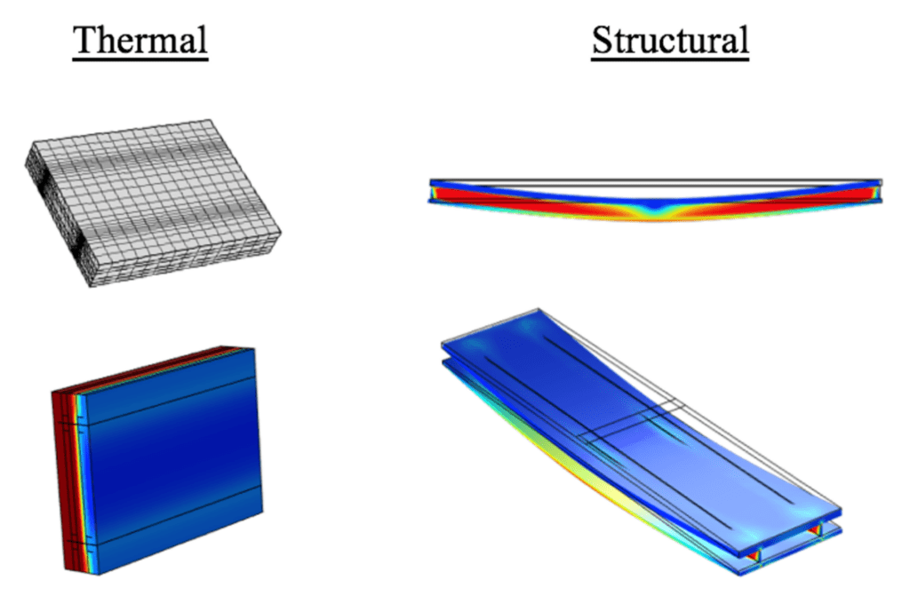
To evaluate the thermal performance of the panels, a sample thin design was experimentally tested using a hot plate apparatus. Finite Element modelling was then used to further investigate the common features of thin panel designs and potential areas of heat loss. The analysed thin sample sandwich panel (150 mm thick) achieves an average U-value of 0.324 W m−2 K−1; this is 16% lower than that of a typical 315 mm thick sandwich panel with 100 mm of polystyrene foam insulation. Thermal bridging was identified as a source of heat loss in the thin wall design, accounting for up to 71% of the total thermal transmittance of the tested thin sandwich panel. In standard walls this is usually less than 20%. Further investigations and design reiterations showed that some of the features of the tested design could be improved to significantly reduce the effect of the thermal bridging and reduce the U-value by 59% to 0.13 W m−2 K−1 in an optimised panel design.
Thermal Testing Finite Element Modelling
These innovations resulted in significant enhancement of sandwich panels and design guidelines and evidence for next generation low embodied carbon, high performance sandwich panels – panels that allow full wall installation in a single, time efficient process.
For more detailed information on the project and accompanying publications click here.
Watch this space for part two by Professor Roger West, coming soon.
Opinion Piece by Guest Author, Paul Iddon ARB RIBA
Creating a building of distinction requires extraordinary design and materials.
Not all buildings are created equal. When it comes to architecture, there are extraordinary briefs and settings that demand an extraordinary response. The interesting thing is that anyone can sense when a building is special, when it has been loved, agonised over, lavished with care and attention to detail. We can feel it in our bones, and we know it matters. The idea of ‘civic pride’ may seem a bit 1950’s, but ask any resident of Barcelona, Sydney or New York and they will tell you in effusive terms of love for their city and what makes it special. As you read this, I can confidently predict you already have a particular building in each case in your head – am I right?
This is the remarkable power of architecture at the highest watermark, it is imprinted on our collective unconscious because it represents the pinnacle of human achievement. Architecture is called the mother of the arts for good reason.
If you have been lucky enough to witness first-hand the genius of Antonio Gaudi’s Sagrada Familia, the innovative triumph of Jørn Utzon’s Sydney Opera House, or William van Alen’s art deco landmark Chrysler Building on Lexington Avenue, you will have been enriched for ever. There are many more all over the world, but you get the point. There is no substitute for quality, and it shows.
Two St Peter’s Square by Simpson Haugh ArchitectsTwo St Peter’s Square by Simpson Haugh Architects
I would add to the list of world-class architecture, some examples closer to home. The magnificent response to the iconic Manchester Town Extension’s stone tracery was lovingly referenced by architect Simpson Haugh at No.2 St. Peter’s Square shown above. It is a building fit for probably the most important public space in the city.
Another stunning example is the Victoria and Albert Museum in Dundee by Kengo Kuma and Associates. A radical addition to the city’s waterfront, with its unmistakable references to the ruggedly beautiful Scottish landscape.
Victoria & Albert Museum, Dundee – Kengo Kuma & AssociatesVictoria & Albert Museum, Dundee – Kengo Kuma & Associates
What do they all have in common?
Remarkable expression through their design and materials. Impact created through a powerful combination of quality, simplicity and clarity of form. To architects and those acquainted with the history of Imperial Rome, the ‘Vitruvian Triad’ is still the measure of architecture and has been for over 2000 years. Developed by Emperor Augustus’ chief architect and military engineer, Marcus Vitruvius Pollio 80-15 BCE and described with beautiful simplicity in three Latin words: Firmitatis, Utilitatis, Venustatis.
These three qualities Vitruvius believed every structure should possess, most commonly translated as Commodity (appropriate design of spatial accommodation and setting on the site, i.e., good planning), Firmness (Stability and build quality i.e., excellence in detail and construction), and Delight (Beauty and attractiveness in appearance). These cases are such an incredible success because they all possess these three simply stated qualities. But achieving them is extraordinarily difficult and is as clear as day when manifested in the world.
When it comes to facades of distinction, it is the second, Firmness, that holds the key to success even with the most brilliant concept. The material from which it is built defines its longevity and resilience to the ravages of climate and time. The examples in Manchester and Dundee use precast concrete manufactured to exacting specification, in order to stand solid and proud in the extremely variable climate of the British Isles, coupled with the environmental challenges of pollutants in North Cheshire basin or exposure and salinity of the Tay estuary.
“To build sustainably, we should build for centuries”
This material is noble, robust and durable. Perfectly in tune with the requirements of the highest quality demanded by the public realm. It is axiomatic amongst architects that sustainable design, especially in buildings of such note, should be based not just on a sensitivity to embodied carbon, but also their resilience and longevity. We should, of course, leave no stone unturned in striving for low carbon materials and a healthy circular economy, but as a first principle, to build sustainably, we should aim to build for centuries. The architecture that means the most to our civilisation, has the quality that last many lifetimes. Is part of the fabric of our shared history.
That means paying attention to the creation of buildings of distinction, with facades of distinction.
Paul Iddon ARB RIBA,
Owner / Director Agency PSI Ltd Vice President – Manchester Society of Architects RIBA NW Council Member
Opinion Piece by Dr. Richard O’Hegarty BE MSc PhD, UCD Research Fellow & Techrete R&D Manager.
After water, concrete is the most consumed substance on the planet. Anything consumed in such large volumes will inevitably leave a dent on the environment. In fact, it is estimated that 7-8% of global greenhouse gas emissions are associated with the cement and concrete industry. But before we discredit concrete, we should consider why it became so popular in the first place.
Why do we use so much concrete?
Mark Miodownik, a material scientist from University College London, wrote a book called Stuff Matters about the fascinating materials that we use on a daily basis. He titles one of the chapters in this book “Fundamental”. This chapter is about concrete, and that is precisely what concrete is. Concrete was fundamental to the growth of past empires, has been fundamental to the growth of today’s modern world powers and will almost certainly be fundamental to the growth of developing countries. It’s found in the roads and train tracks that connect us together, the water and sewerage systems that plumb our towns and cities and also the foundations of the towers that transport our energy. It’s in the buildings in which we live, work and socialise. Concrete is used everywhere. It does not require highly skilled labour, it’s made from relatively cheap abundant materials and can be moulded into virtually any shape.
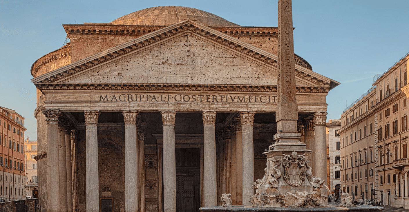
Concrete is also incredibly durable. The pantheon was constructed by the Romans almost 2,000 years ago yet still stands strong today. Other construction materials cannot compete with concretes’ longevity. In fact, it is the corrosion of the steel in modern reinforced concrete that determines its design life. The typical design life of steel reinforced concrete is 50-100 years, while concrete alone could last over 1000 years.
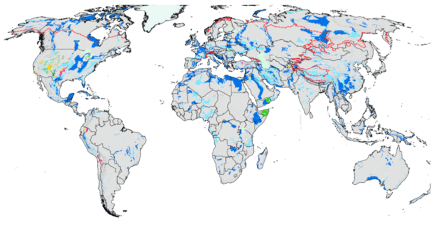
The Pantheon, RomeLimestone Hotposts (Photo credit Geological Survey)
The materials concrete is made from are abundant. Cement is primarily made from limestone and the earth’s crust is 15% limestone. The aggregates and sands used in concrete can be made from both crushed rock and natural sands/gravel from glacial deposits or marine/river beds. The latter option is depleting in some parts of the world, but crushed rock is generally plentiful. The merits of concrete extend far beyond these points. The simple fact that it is so widely used is in itself evidence of its success as a building material.
But here’s the problem:
Concrete’s popularity comes at an environmental cost. Cement, the key ingredient in concrete which glues the pieces of rock and sand in concrete together, is manufactured by burning limestone at extremely high temperatures in a large cylindrical chamber called a kiln. This process results in CO2 emissions from both the chemical change of materials in the kiln and the combustion of the fuel used to reach these temperatures. So it is cement1 rather than concrete which is the primary cause of its environmental impact. In short, we simply cannot continue making concrete the same way as we have done in the past and expect its associated greenhouse gas emissions to reduce.
Ok…but what are the solutions?
It is incredibly unlikely that there will be one single solution that will overcome the carbon intensity associated with the manufacturing of modern day concrete, but rather it will take a collective innovative effort from all groups of people. Research scientists will be required to develop new scalable cement and concrete formulations, engineers will be now tasked with pushing the limitations of structural efficiency to remove redundancy, while policy makers have to enable change through a modernisation of potentially out-dated standards.
The cement we use needs to be manufactured with less clinker. The kilns we use to melt limestone need to be fuelled by low carbon fuels. The concrete elements we design need to be thinner and more efficient than ever and carbon capture and storage needs to be advanced.
A number of research groups (both academic and industry lead) are tackling each individual component in this jigsaw of solutions. To date, many promising individual results have been obtained.
Clinker Substitution & Cement Replacements
I previously mentioned that cement was the problem rather than concrete. This is true, however it’s only part of the story. The raw material produced from these gigantic cylindrical ovens is called clinker, and the more clinker in a cement blend, the more carbon intensive that cement will be. Most cements are a blend of clinker and other materials including limestone fines, slag and ash. A number of companies are leading the way when it comes to the clinker-substitution route to net zero. Ecocem, for example, are developing scalable ultra-low clinker cements while Wagners, an Australian company, are driving the use of a zero clinker concrete – better known as geopolymer.
Zero Carbon Fuel Kilns
The other big emitter of carbon, when it comes to clinker production is the burning of fuel, required to reach the high kiln temperatures. A project lead by the Mineral Products Association (MPA), Hanson UK and funded by the Department for Business, Energy and Industrial Strategy (BEIS) in the UK is working on a solution for just that. And for the first time in history a cement plant has produced clinker from a net zero fuel. Ribblesdale cement plant in the UK, ran a production cycle using hydrogen and bio fuel, proving that emissions could indeed be cut. Economically scaling this will be a challenge but the potential is definitely there.
Efficient Structural Design
When it comes to design efficiency, many examples exist. Cheap materials like concrete have historically meant that it was the cost of programming a solution that dictated design – rather than the cost of the material itself. If the cost of finding a solution to a complex structural problem was too great, the cheaper option was to de-optimize the structural design and add more material. Advancements in computers over the past three decades have meant that the software and hardware used to simulate the structural stresses and strains in complex designs have become more accessible and so this is no longer the barrier it once was.
Our built environment is generally created from angular prismatic elements – not because these are structurally optimal but because these shapes are easy to engineer and manufacture. The geometry of our future cities will better represent nature, which, after all, has been developed from a finely tuned algorithm optimised over millennia. A number of research groups are getting closer with these designs.
A UKRI funded research group of engineers, mathematicians and manufacturing experts from Universities of Bath, Cambridge and Dundee have developed a thin shell vaulted floor which uses 75% less concrete than a traditional slab with equivalent strength, thereby reducing the carbon footprint by 60%. While another group of researchers from ETH Zurich have been developing a rib-stiffened funicular flooring system that saves 70% of the concrete, and 90% of the steel reinforcement of a conventional slab.
Removing structural redundancy, reducing clinker consumption and decarbonising the energy used to produce the raw materials of concrete will all play an important role in squeezing carbon out of the industry. However, even in the most positive scenario for the three routes listed above a remainder of carbon will likely be left over, and therefore, a fourth major piece is necessary.
Carbon capture, storage and utilization is a key component in both the Global Cement and Concrete Association (GCCA) and the Cembureau’s roadmaps to carbon neutrality by 2050 for the cement and concrete industry.
Essentially there are, (as the name suggests), three key stages to making this whole process work.
First, the carbon must be captured, and while nature has already come up with a solution for this through trees and vegetation, it did not plan for humans to emit so much carbon, hence other solutions are needed to capture carbon. There are two main types of non-natural carbon capture: direct air carbon capture and local carbon capture, the latter being most relevant to the concrete and cement industry. Local carbon capture focuses on emitted carbon at the source of production. Three main types of carbon capture exist here (pre combustion, post combustion and oxyfuel)2 – the solution most suited to concrete being post combustion which captures the CO2 from the flue gases.
Once captured, the carbon then needs to be transported3 to a site where it will be either stored or used. Carbon can be stored in deep geological rock formations (similar to those formations where we extracted the fuel used in the first place) or could be used as a commodity (carbonated drinks, fire extinguishers, fuel recovery etc). The issue with the former solution (storage) is the cost and potential for leakage. With regard to the second solution (utilisation of carbon) the main challenge is to find something which we use in such large volumes that matches the rate at which we emit carbon. Whatever utilization solution we come up with will have to be used in huge volumes. And what do we use a lot of? Oh yeah….concrete!
Using CO2 in concrete is precisely the route Blue Planet Systems® are taking. They are mixing captured CO2 with water-based solutions to form synthetic limestone which can be used to make concrete. This would make concrete a carbon sink rather than carbon source. So perhaps concrete will be the solution rather than the problem!
The Future of Concrete is…
The challenge of decarbonizing concrete is huge, but the significant increase in awareness has instilled confidence in me. The sheer volume of concrete consumption means that sometimes small improvements adopted at scale are more impactful than ground-breaking innovations which cannot be scaled. Every innovative effort (big or small) made to remove carbon from concrete should be considered. In my opinion, the future of concrete will involve using a combination of solutions. I don’t know the precise recipe to these solutions, but I do know we are all now looking hard.
‘The vertical thinker says: “I know what I am looking for”. The lateral thinker says: “I am looking but I won’t know what I am looking for until I have found it”’ – Edward de bono
This is an exciting time to be working with concrete because there is no choice, the industry either innovates together or gets left behind.
It is actually the raw material most cements are made from – discussed later.
A topic for another day
This transport cannot be more polluting than the carbon it is transporting.
Geological Survey full photo credit : World distribution of karstifiable rocks (Chen et al, 2017) – Source: Chen Z., Auler A., Bakalowicz M., Drew D., Griger F., Hartmann J., Jiang G., Moosdorf N., Richts A., Stevanovic Z., Veni G.,& Goldscheider N. 2017 The World Karst Aquifer Mapping Project – Concept, Mapping Procedure and Map of Europe. Hydrogeology Journal, 25, 771-785.”